
Installation,
Warranty & Servicing
Our expert team provides comprehensive installation services to ensure your medical equipment is set up efficiently and correctly.
Select Product
Introduction
This guidance describes the general information to prepare a site for installing a Koning Breast CT (KBCT) system. This manual is for Koning customers, technical representatives, and field service engineers. Any questions regarding these instructions should be brought to the attention of Koning Corporation or Koning’s Authorized Representative.
Site Environmental Requirements
Operating temperature range throughout the KBCT suite is 68 ºF (20 ºC) to 75 ºF (24 ºC) at 30% to 60% relative humidity (non-condensing). Heat output in one area of the suite must not affect temperature and humidity in other areas. It is strongly recommended that any definable areas within the suite, i.e., equipment closets, control areas, etc. (if applicable), be environmentally controlled on an individual basis as required to meet the ambient ranges specified.
Total cooling requirement for the KBCT system workplace is approximately 19,100 BTU/h. This does not include cooling for room lighting, personnel or other non KBCT system considerations. This is calculated on a 5% scanner duty cycle.
A sink with cabinet and counter space, etc., may be required by Local Codes or desired by customer in each exam room. A toilet adjacent to CT room may also be required by Local Codes or desired by customer. These items of convenience are not required for the operation and use of the Koning Breast CT System. Consult with local authorities for codes and requirements.
It is suggested that oxygen and suction services be provided in exam room at a location with convenient access to the Scanner. Oxygen and suction may be portable or permanent. Fire protection for the type of equipment and systems specified shall be provided in accordance with local codes.
Power Requirements
All power conditioning and surge suppressor equipment provided by the facility shall be installed according to manufacturer's specifications and installation instructions. Some devices may require additional external fuse protection. All work shall comply with Local Codes.
- Supply Configuration: Single Phase, 2 Wire power and Ground
- Nominal Line Voltage: 208/220/240 VAC, 35A maximum, 50/60 Hz
- Regulation: 3% Maximum
Power supplies for patient automatic power injector systems should derive from a ground potential equal to the System, if applicable.
Locate power conditioners, step-down transformers or isolation transformers provided by the facility as close to the KBCT system power cabinet as possible.
A disconnecting means shall be provided.
Electrical
Ducts
and Boxes
Electrical ducts and boxes shall be accessible and have removable covers. Floor ducts and boxes shall have watertight covers. It is recommended ducts be divided into separate channels by metal dividers, to separate wiring and/or cables into groups, e.g. power wiring and/or cables, and signal and/or data and protective ground wiring and/or cables.
Conduit
Electrical ducts and boxes shall be accessible and have removable covers. Floor ducts and boxes shall have watertight covers. It is recommended ducts be divided into separate channels by metal dividers, to separate wiring and/or cables into groups, e.g. power wiring and/or cables, and signal and/or data and protective ground wiring and/or cables.
Note
Heavy duty cable protection equipment must be available for pedestrian traffic areas where cables are exposed, running from the Power Cabinet to the Scanner and Power Cabinet to the Operator’s Console.
Network/IT Requirements
The KBCT system requires two (2) unique IP addresses which should connect to the designated RIS and PACS system for worklist query, image storage, archive and viewing. Failure to provide unique IP addresses may result in a network conflict and the improper function of some features.
A dedicated network connection to the KBCT system operator’s console with Koning access through any firewall is recommended for remote service diagnosis.
Koning Image Rendering Server
The KBCT image rendering server should be able to be accessed from the radiologists’ workstations.
If the site provides the hardware, either physical workstation/server or virtual machine, for the KBCT image rendering server, the recommended minimum configuration for three (3) concurrent users is as below.
- RAM: 64G RAM
- CPU: 24 Cores @2.0GHz
- Storage: 2TB
Power supplies for patient automatic power injector systems should derive from a ground potential equal to the System, if applicable.
Please contact Koning Corporation or Koning’s Authorized Representative for other configurations.
Radiation Protection
The KBCT system is self-shielding due to its highly collimated low energy X-ray beam, 1/16” Pb primary barrier behind the detector and lead plated covers. Also, the optional Operator’s Console has a minimum 0.8 mm Pb equivalent barrier. The Site shall obtain the service of a licensed radiation physicist to specify any additional radiation protection.
Radiation Scatter Survey Information
Survey results were obtained under the following conditions:
- All measurements were taken during a 10 second normal circle scan at the indicated positions (see Figure 8.4-1) and at tabletop level (~4’ or ~1.2 m above the floor)
- Phantom: 16 cm diameter, 15 cm high acrylic phantom (CT head dose phantom) imaged at the axis of rotation
- Koning breast phantom imaged at the axis of rotation
- Maximum scan parameters (49kVp, 160mA) for full scan
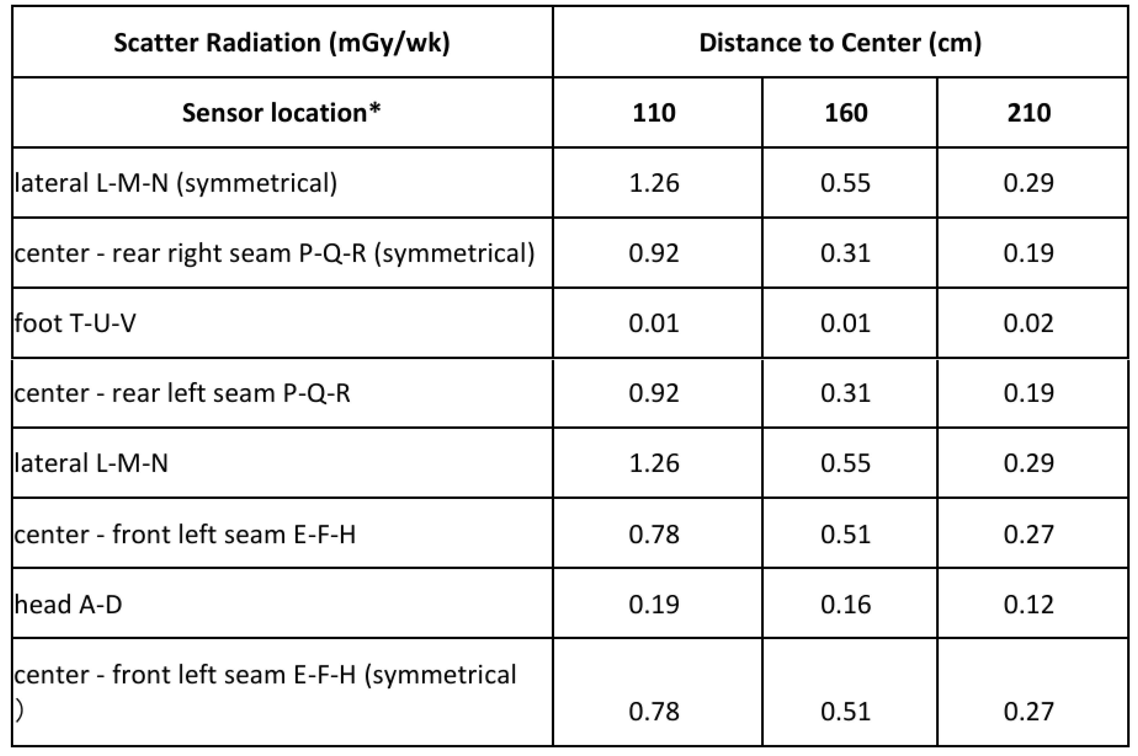
Typical average values for scans at the indicated positions are shown in Table 8.4-1 (measured with an Unfors Xi Dosimeter system)
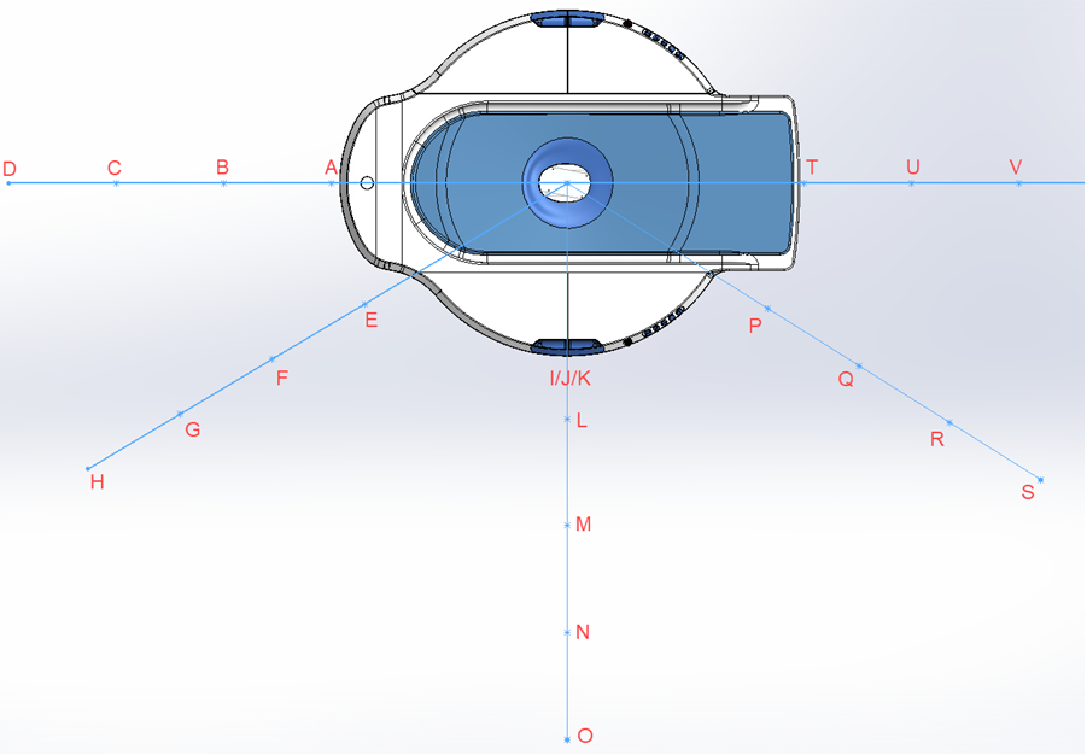
FIGURE 1: Radiation scatter survey diagram
- Symmetrical testing points not shown
- Sensor at the same height as the X ray tube focus spot.
Anchoring for Seismic Conditions
No anchors or anchor bolts for securing the system will be supplied unless seismic conditions are present and anchoring is required by Local Codes. Contact Koning Corporation or Koning’s Authorized Representative for anchor guidance if required.
Note
To meet electrical ground isolation requirements, all methods of anchoring the system must not come in contact with any building steel structure or reinforcement. Modular building floor structures may require additional bracing beneath the Scanner to eliminate vibrations that can affect clinical images.
Floor Loading and Surface
The KBCT system scanner weights ~2200 lbs (1000 kg), and the KBCT system power cabinet weights ~275 lbs (125 kg). The location of the feet on the scanner is shown below.
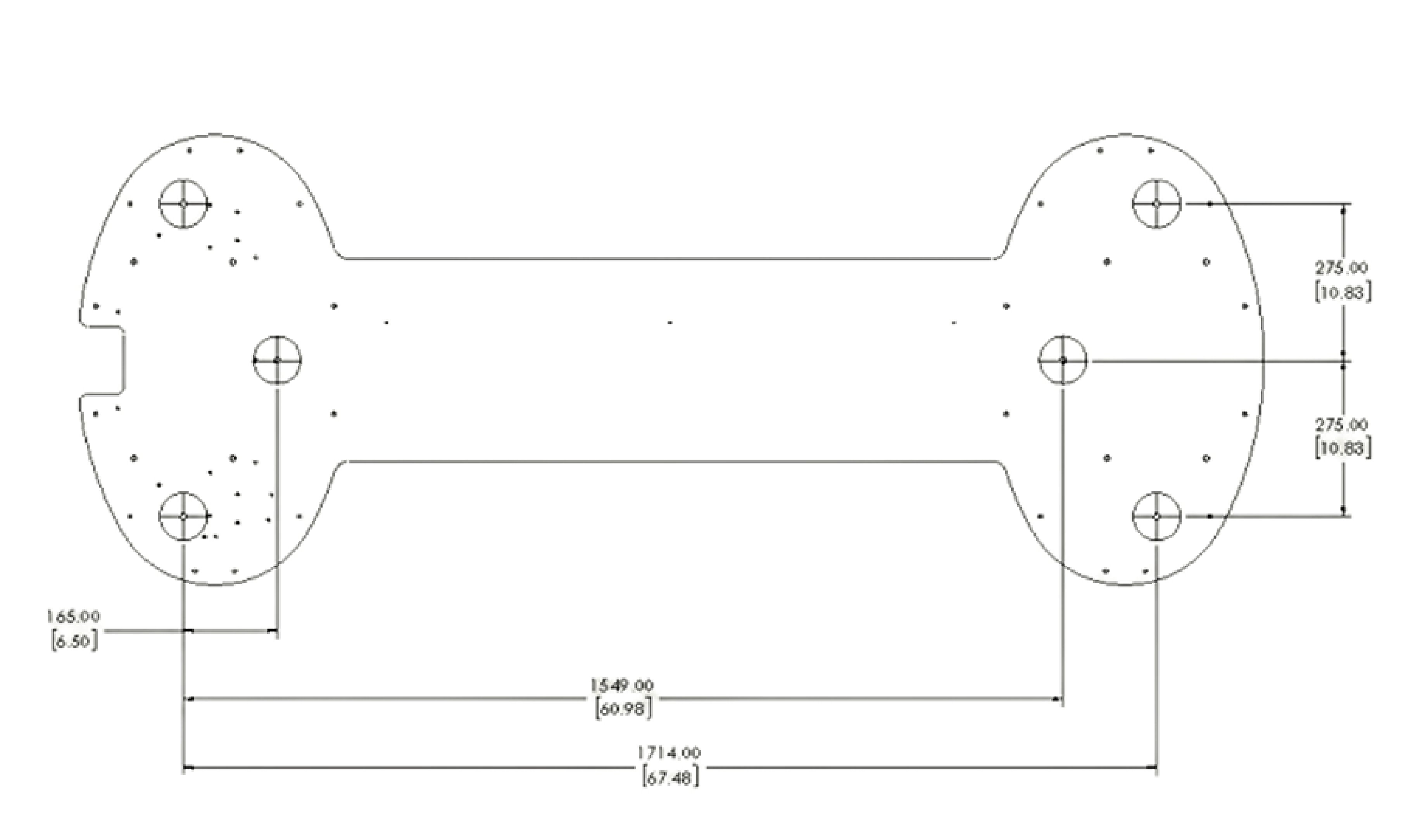
FIGURE 2: KBCT scanner feet location
Note
Weights may vary, within approximately 15% of weight given.
The customer shall be solely responsible, through the engineer of record for the building, to provide, on the architectural/construction drawings, confirmation of the structural adequacy of the floor upon which the equipment will be placed. Any load test required by local authorities shall be the customer's responsibility.
Floor Surface
The floor surface upon which KBCT system scanner is to be placed/anchored shall be flat and level to within plus or minus 1/16 inch (2 mm).
System Dimensions
The KBCT system contains three subsystems, the scanner, the power cabinet and the operator console. The dimension of each subsystem is shown below.
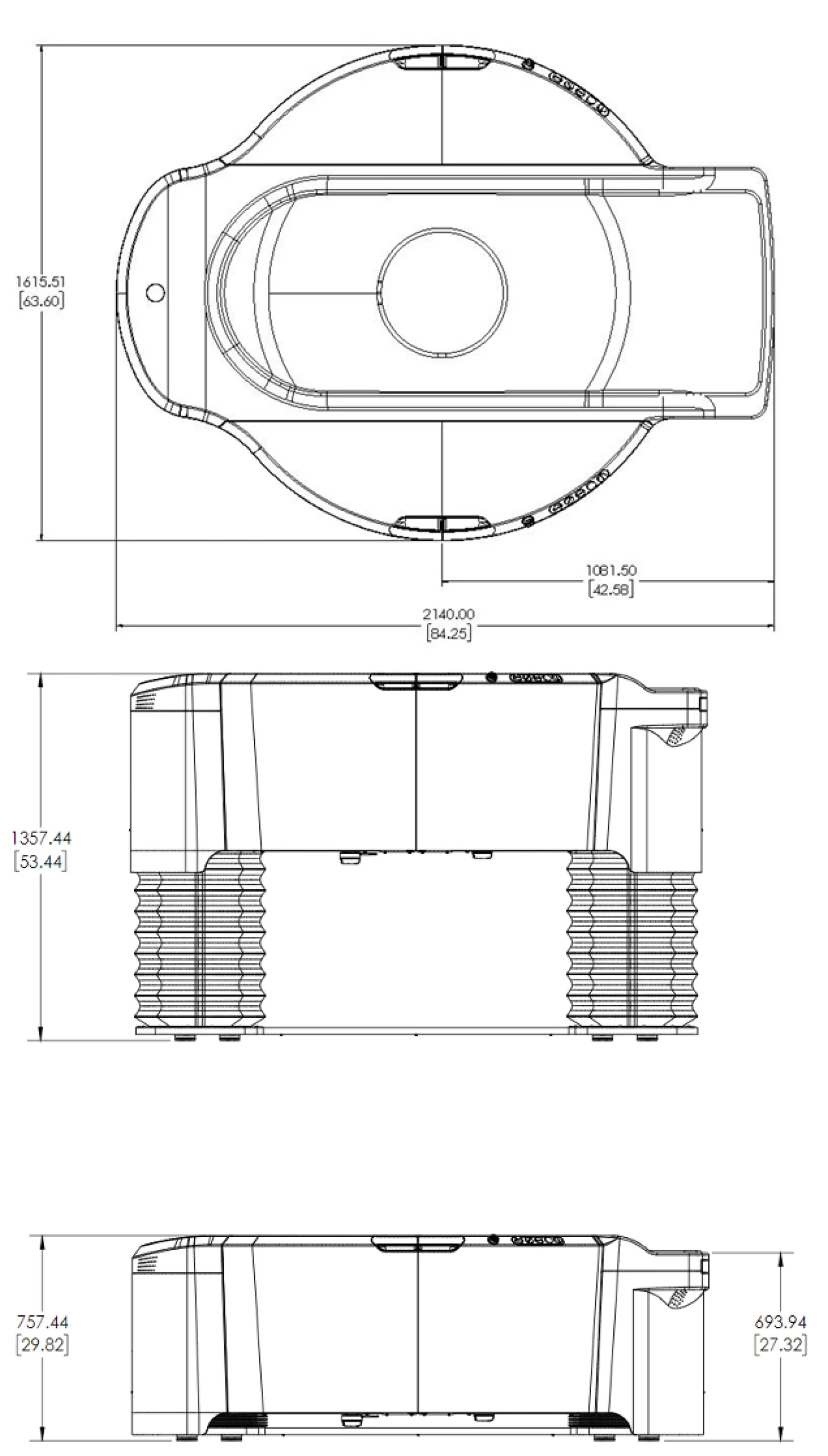
FIGURE 3: The dimension of the scanner (with and without table raised)
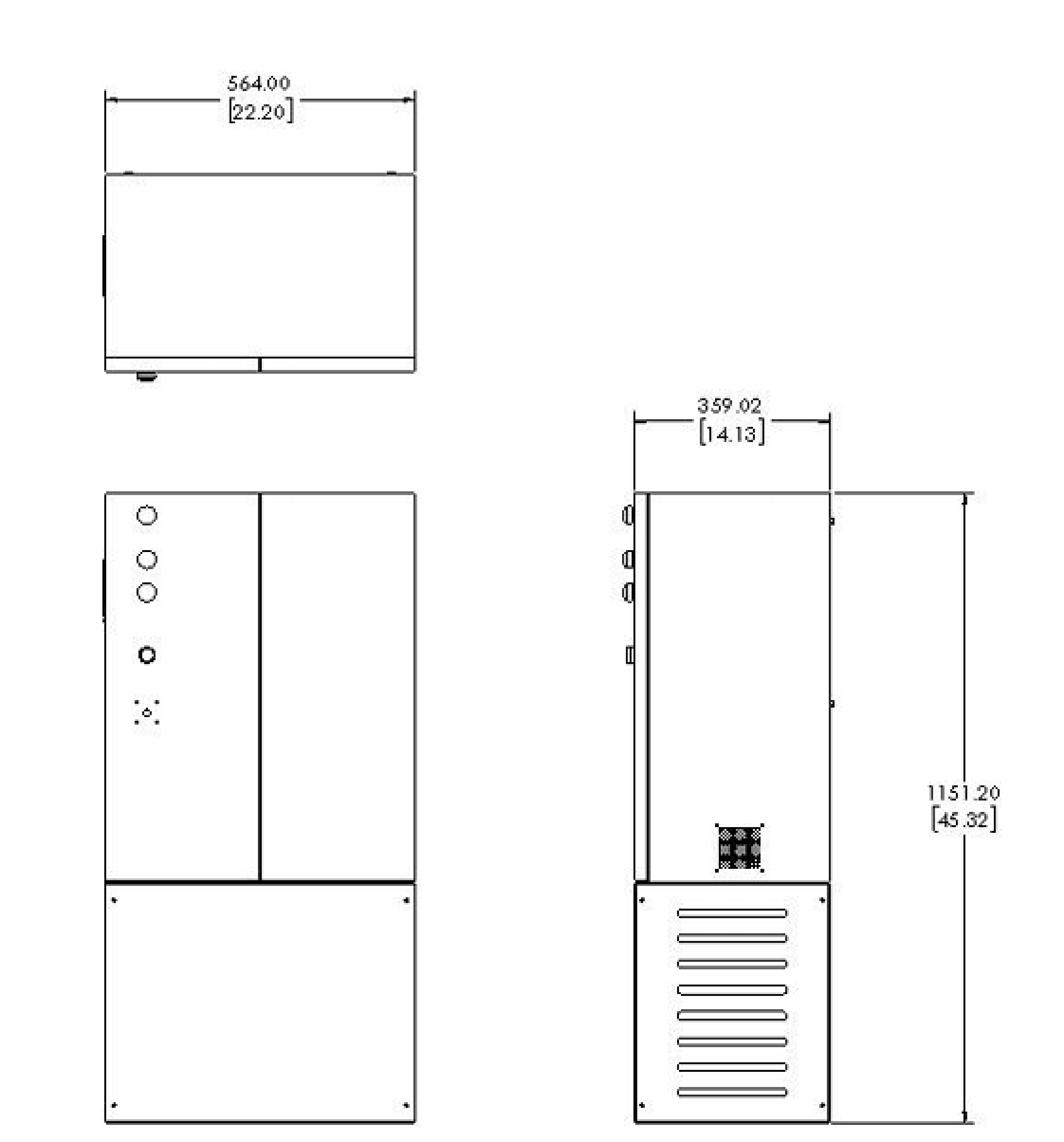
FIGURE 4: The dimension of the Power Cabinet
Room Layout
The room layout for the KBCT System including recommended room size and space requirements shown in the following diagram is based on the necessary accessibility to machine functions by both operators and maintenance personnel.
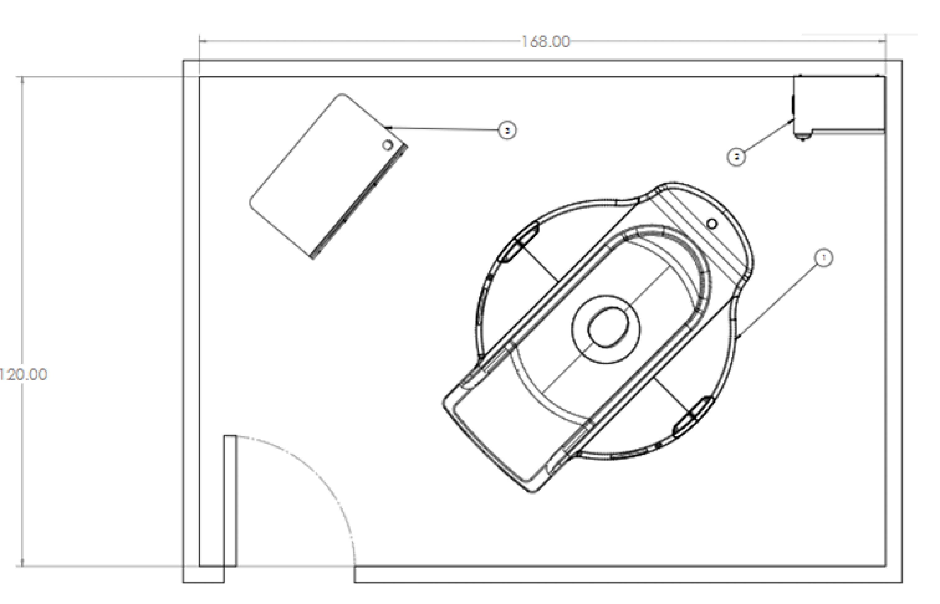
FIGURE 5: Example Room Layout (Room Size: 10’x16’)
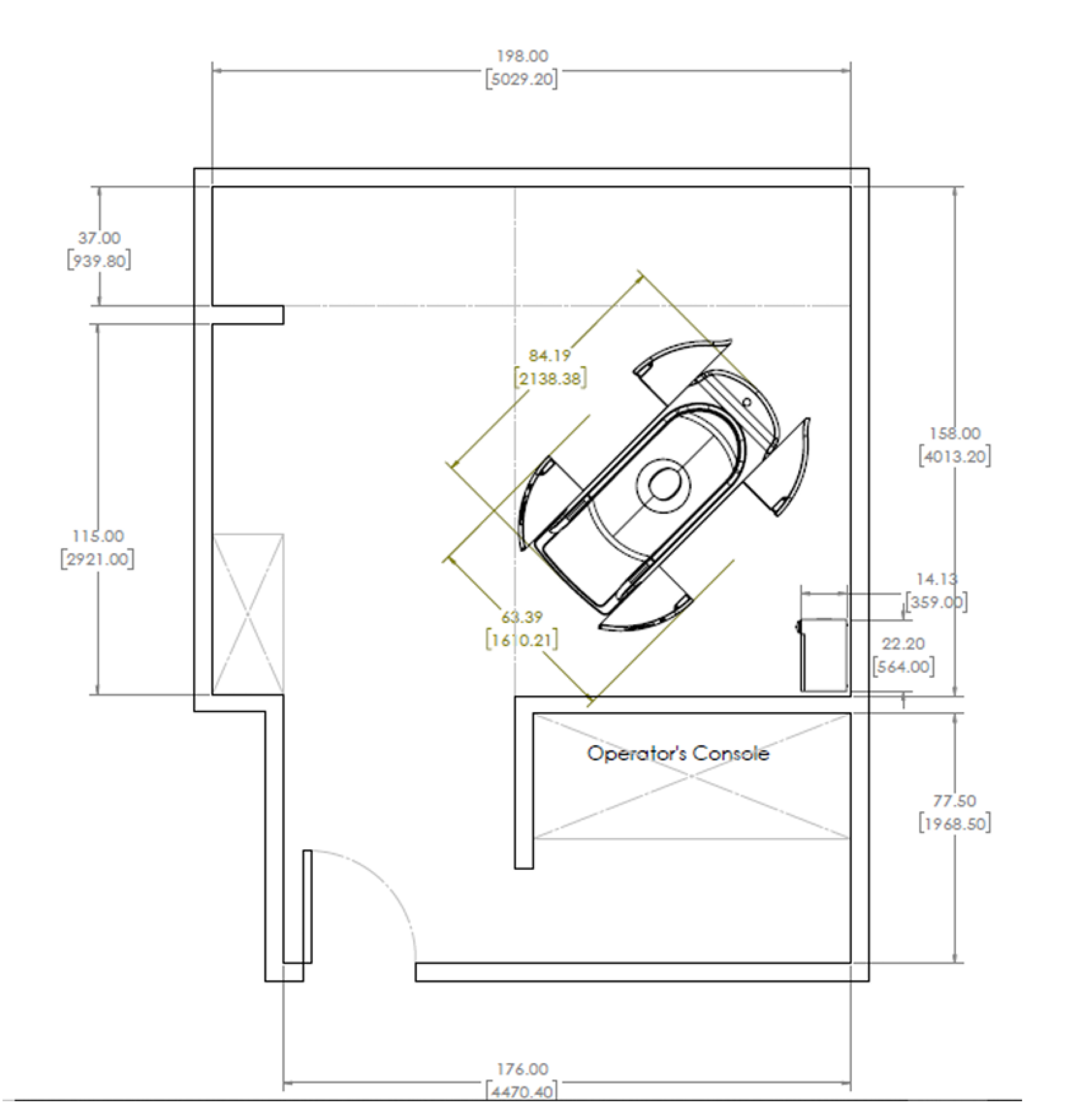
FIGURE 6: Example Room Layout (CT Suite w/ included Operator Room)
- There shall be no obstructions that project below the finished ceiling in the area above the Scanner. Required ceiling height of the room where equipment shall be installed is 96” (244 cm) minimum.
- Door opening clearance for moving equipment into the building must be 48” wide x 84” high (122 x 213.3 cm).
- Door opening required for moving equipment into the room requires a 60 – 72” (152.4 – 182.9 cm) wide corridor with a minimum 36” (91.4 cm) wide (based on straight access, 48” or 122 cm recommended) x 84” (213.4 cm) high door opening. If the scanner needs to turn in a corridor to enter the room the minimum door width may need to be wider, depending on the width of the corridor.